It provides an exclusive electrical signal path for any two network nodes that access the switch. The most common switch is an Ethernet switch. Other common ones are electric Hua voice switches, fiber switches, and so on.
A switch is a LAN that uses a very wide range of network devices and multiple network devices. The switch is an essential device.
Various switch interfaces
The interface of the switch is very rich. Here are some sorted materials to share with you.
1, RJ-45 interface
This interface is the most common network device interface we have now, commonly known as “Crystal Head”, the terminology is RJ-45 connector, which is a twisted pair Ethernet interface type. The RJ-45 plug can only be inserted in a fixed direction, with a plastic dome attached to the RJ-45 slot to prevent it from falling out.
This interface can be used in 10Base-T Ethernet, 100Base-TX Ethernet, 1000Base-TX Ethernet, and the transmission medium are twisted pair. However, depending on the bandwidth, the medium also has different requirements, especially 1000Base- When connecting to a Gigabit Ethernet connection, use at least a Category 5 cable. To ensure stable high speed, use Category 6 cable.
2, SC fiber interface
The SC fiber interface has been used in the 100Base-TX Ethernet era, so it was called 100Base-FX (F is the abbreviation of fiber word fiber), but at that time, because the performance is not more prominent than the twisted pair, but the cost is higher, so Not popularized, the industry is now promoting Gigabit networks, and SC fiber interfaces are re-emphasizing.
There are many types of fiber interfaces. The SC fiber interface is mainly used in the office network switching environment. It is provided on some high-performance Gigabit switches and routers. It looks similar to the RJ-45 interface, but the SC interface is flatter. The obvious difference is the contact inside. If it is 8 thin copper contacts, it is the RJ-45 interface. If it is a copper column, it is the SC fiber interface.
3, AUI interface
The AUI interface is specially used to connect thick coaxial cables. On the early network cards, such interfaces were connected to hubs and switches to form a network, which is generally not used now.
The AUI interface is a “D” type 15-pin interface. It was previously used in a Token Ring or Bus type network. It can be connected to a 10Base-T Ethernet network by means of an external transceiver (AUI-to-RJ-45). Connection.
4, FDDI interface
FDDI is one of the high-speed transmission technologies in mature LAN technology. It has the characteristics of a timing token protocol and supports multiple topologies. The transmission medium is an optical fiber.
The Fiber Distributed Data Interface (FDDI) is a set of protocols developed by the American National Standards Institute (ANSI) to transmit digital signals over fiber optic cables. FDDI uses dual-ring tokens and can transmit at 100Mbps.
CCDI is a variant of FDDI that uses twisted-pair copper cables as the transmission medium and typically has a data transmission rate of 100 Mbps.
FDDI-2 is an extended protocol of FDDI, supporting voice, video and data transmission. It is another variant of FDDI, called FDDI full-duplex technology (FFDT), which uses the same network structure as FDDI, but the transmission rate can reach 200Mbps.
Because the use of optical fiber as the transmission medium has many advantages such as large capacity, long transmission distance, strong anti-interference ability, etc., it is often used in the environment of the metro network, campus environment backbone network and multi-building network distribution, so FDDI interface is in the network backbone switch. It is more common, and now with the popularity of Gigabit, some high-end Gigabit switches also use this interface.
5, Console interface
This interface we know, it is used to configure the switch, so only the network management switch. Also note that not all network management switches are available because there are various ways to configure the switch, such as Telnet command line mode, Web mode, and TFTP mode. Although in theory, the basic configuration of the switch must pass through the Console port, the basic configuration of some brands of switches is configured at the factory and does not require basic configuration such as IP address and basic user name. Therefore, such a managed switch does not need to provide this Console interface, and it is still the majority. Such switches usually only need to perform some advanced configuration through a simple Telnet or Java program web.
Of course, some switches still provide a console interface, but it should be noted that the console port used for switch configuration is not the same as all switches, and some use the same RJ-45 type Console interface as the Cisco router, while others Use the serial port as the console interface.
As can be seen from the figure, the console ports of the two switches are different. In the above figure, there is a “female” head 9-hole “D”-shaped interface, and the following figure is a “male” head 9-pin “D” type interface. They are commonly known as “DB-9” interfaces, but they are all configured for switch configuration.
Switch connection method
Because the switch is mainly used as a centralized connection of LAN devices, in general, the hardware connection is relatively simple, and usually, only the corresponding transmission medium connector is inserted into the corresponding switch interface. The following is a brief introduction to the connection method of switch cascading.
This is the most common way to connect multiple switches, which is connected via the cascade port (UpLink) on the switch. Note that the switch cannot be cascaded indefinitely. If a certain number of switches are cascaded, the broadcast storm will eventually cause a serious drop in network performance. The cascade is divided into the following two types:
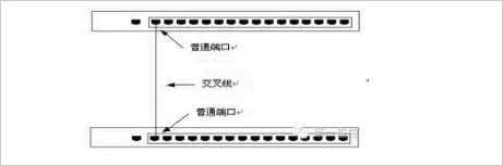
1, using the common port cascade
The so-called common port is connected through a common port of the switch (such as RJ-45 port). It should be noted that the connected twisted pair cable used at this time should be reversed, that is, the two ends of the twisted pair should be jumpered (the first and second legs are reversed). The connection is shown as shown.
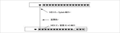
2, using Uplink port cascading
In all switch ports, there will be an Uplink port next to it, as shown in Figure 2. This port is provided for the uplink connection. Simply connect the port to any port on the other switch except the “Uplink port” through the straight-through twisted pair (note that the Uplink ports are not connected to each other).
The connection is shown in the figure below.